
Subsea Design and Engineering
Subsea refers to the environment and infrastructure located on the ocean floor, typically at depths greater than a few metres where conventional surface‑based operations are not feasible. The design and engineering of subsea systems must ad…
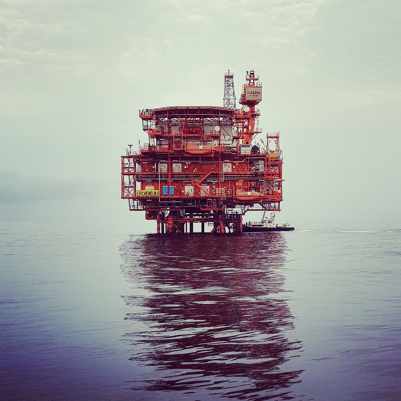
Subsea refers to the environment and infrastructure located on the ocean floor, typically at depths greater than a few metres where conventional surface‑based operations are not feasible. The design and engineering of subsea systems must address high hydrostatic pressure, low temperatures, corrosive seawater, and limited accessibility for inspection or repair. A common practical application is the installation of a flowline that transports produced hydrocarbons from a wellhead to a processing facility onshore or on a floating production unit. One of the biggest challenges in subsea work is ensuring the integrity of the system over its intended service life despite the harsh environment.
Riser is a vertical or inclined conduit that connects the seabed equipment to surface facilities, allowing the transfer of fluids, power, or control signals. Risers can be classified as drilling risers, production risers, or service risers depending on their function. For example, a steel catenary riser (SCR) is a flexible pipe that follows a catenary shape due to its own weight and is widely used in deep water production systems. Designing a riser involves calculating the dynamic response to vessel motions, vortex‑induced vibrations, and fatigue life. Engineers must also consider the interaction between the riser and the marine environment, such as the effect of sea currents on the riser’s tension and the risk of marine growth.
Flowline is a pipeline that conveys oil, gas, or water between subsea equipment such as wells, manifolds, and processing facilities. Flowlines are often made of carbon steel, stainless steel, or composite materials, and may be insulated to prevent hydrate formation. A typical challenge is managing the pressure drop along the flowline while maintaining the required flow rates. For instance, a long‑distance flowline may require the use of boosting stations or the installation of a subsea pump to overcome frictional losses.
Umbilical bundles together hydraulic, electrical, and fiber‑optic lines that provide power, control, and communication to subsea equipment. Umbilicals are usually deployed in a single jacketed pipe to protect the individual cables from mechanical damage and corrosion. An example of an umbilical application is the supply of hydraulic power to a subsea tree’s actuators for opening and closing the valves. The design challenge lies in ensuring that the umbilical can withstand the combined stresses of tension, bending, and pressure while maintaining signal integrity over long distances.
Subsea Tree, also known as a Christmas tree, is an assembly of valves, chokes, and sensors that sits on top of a subsea wellhead to control the production flow. The tree allows for safe start‑up, shut‑down, and flow regulation without the need for surface intervention. A typical tree might include a master valve, a swab valve, and a choke valve. Practical challenges include ensuring the reliability of moving parts in a corrosive environment and providing adequate redundancy to meet safety standards.
Manifold is a junction point where multiple flowlines converge and are distributed to a common processing point or to a production riser. Manifolds can be simple tees or complex multi‑port assemblies with integrated valves and instrumentation. In a field with several wells, a manifold simplifies the routing of fluids and enables individual well control. The design must consider pressure balancing among the connected wells and the need for isolation in case of a leak.
Wellhead is the structural and pressure‑containing component that sits on the seabed and provides the interface between the drilling or production equipment and the geological formation. Subsea wellheads are usually made of high‑strength steel and are equipped with seals, connectors, and mounting points for trees or manifolds. A common design challenge is ensuring the wellhead can tolerate the high cyclic loads caused by drilling operations and the thermal expansion of the surrounding environment.
Seafloor is the physical surface on which all subsea infrastructure is installed. The geotechnical properties of the seafloor, such as sediment type, shear strength, and bearing capacity, influence the selection of foundations for equipment. For example, a gravity base may be used for a lightweight manifold on soft clay, while a pile‑supported structure is required for heavier riser jackets on stiff sand. Engineers must also evaluate the risk of seafloor movement due to currents, sediment transport, or seismic activity.
Hydrate formation is a major flow assurance issue in cold deep‑water environments. Gas hydrates are crystalline compounds that can block pipelines, leading to flow restrictions or even full shutdowns. To mitigate hydrate risk, operators may inject methanol or glycol inhibitors, maintain the pipeline temperature above the hydrate formation point, or use insulated flowlines. Designing an effective hydrate‑prevention strategy requires a thorough understanding of thermodynamic conditions and fluid composition.
Corrosion is the degradation of metal surfaces due to electrochemical reactions with seawater, which can lead to thinning, pitting, and eventual failure. In subsea engineering, corrosion control strategies include the use of corrosion‑resistant alloys, protective coatings, and cathodic protection (CP). CP involves applying a small electrical current to the metal structure to make it the cathode of an electrochemical cell, thereby reducing its corrosion rate. Monitoring CP effectiveness is critical and often performed using reference electrodes and potential measurements.
Fatigue refers to the progressive and localized structural damage that occurs when a material is subjected to cyclic loading. Subsea components such as risers, flowlines, and umbilicals experience fatigue due to wave‑induced motions, vortex shedding, and pressure fluctuations. The fatigue life of a component is usually estimated using an S‑N curve (stress versus number of cycles) and a damage accumulation model such as Miner’s rule. Engineers must design for sufficient fatigue margin, often by selecting appropriate material grades, adding reinforcement, or applying damping devices.
Vortex‑Induced Vibration (VIV) is a phenomenon where alternating vortex shedding creates oscillating forces on a cylindrical structure, leading to resonant vibrations. VIV can significantly reduce the fatigue life of risers and flowlines. Countermeasures include the use of strakes, helical ribs, or helical fairings that disrupt vortex formation. Accurate VIV prediction requires computational fluid dynamics (CFD) analysis and experimental validation in water tunnels.
Dynamic Positioning (DP) is a ship‑based technology that uses thrusters and computer control to maintain a vessel’s position and heading without anchoring. DP is essential for the installation and maintenance of subsea equipment in deep water where anchoring is impractical. The reliability of DP systems is assessed using DP class standards, which define redundancy requirements for power, control, and sensor systems. A failure in DP can lead to equipment collision or loss of alignment during installation.
Installation Vessel is a specialized ship equipped with heavy‑lift cranes, DP systems, and subsea deployment equipment such as ROVs (remotely operated vehicles). Installation vessels are used to lay pipelines, place manifolds, and attach trees to wellheads. The selection of an appropriate vessel depends on water depth, payload capacity, and the complexity of the project. For example, a float‑over vessel can install large templates by floating them over the seafloor and lowering them into position.
Remotely Operated Vehicle (ROV) is an unmanned underwater robot that provides visual inspection, intervention, and tool handling capabilities. ROVs are indispensable for subsea construction, maintenance, and de‑commissioning tasks. They can operate at depths exceeding 3,000 metres and are equipped with manipulators, sonar, and high‑definition cameras. An example of an ROV application is the connection of an umbilical to a subsea tree using a hot‑stiched splice.
Hot‑Stiched Splice is a method of joining two subsea umbilical sections by heating the polymer jacket, aligning the conductors, and then fusing them together. This technique provides a strong, watertight connection without the need for mechanical couplings. The splice must be tested for tensile strength, electrical continuity, and pressure integrity before being certified for deployment.
Template is a pre‑engineered steel frame that holds multiple subsea components such as manifolds, trees, and valves in a predetermined arrangement. Templates are lowered to the seafloor and anchored, allowing rapid installation of complex infrastructure. A challenge associated with templates is ensuring precise alignment of all connection points to avoid mis‑fits that could lead to leaks or operational delays.
Subsea Production System (SPS) encompasses all equipment required to extract, process, and transport hydrocarbons from the seabed to a surface facility. An SPS typically includes wellheads, trees, manifolds, flowlines, risers, and control systems. The integration of these components must consider hydraulic performance, reliability, and maintainability. Lifecycle management of an SPS involves design, installation, operation, monitoring, and eventual de‑commissioning.
Control System in subsea engineering refers to the hardware and software that monitor and regulate the operation of subsea equipment. This includes pressure and temperature sensors, valve actuators, and communication links via the umbilical. A common architecture is the Distributed Control System (DCS), which allows local processing at the subsea node and remote supervision from the surface. Ensuring real‑time data transmission over long distances and under high pressure is a key challenge.
Pressure Sensor is a device that measures the hydrostatic or process pressure within a subsea pipeline or wellhead. Pressure data are essential for flow control, safety shutdowns, and performance optimization. Sensors must be calibrated to operate accurately at temperatures as low as 4 °C and pressures up to 10 MPa. Failure to obtain reliable pressure readings can lead to unsafe operating conditions.
Temperature Sensor provides critical information for flow assurance, especially in cold deep‑water fields where hydrate formation is a risk. Thermocouples and resistance temperature detectors (RTDs) are commonly used, each with different accuracy and response characteristics. Sensors are often placed in proximity to flowlines and manifolds to enable proactive heating or inhibitor injection.
Valve Actuator is a device that provides the mechanical force required to open or close a subsea valve. Actuators can be hydraulic, electric, or electro‑hydraulic. Hydraulic actuators are favored for their high force capability and reliability in deep water. The design must account for the pressure differential across the valve, the required torque, and the need for fail‑safe operation.
Fail‑Safe design ensures that a component or system defaults to a safe condition in the event of a failure. For subsea valves, a fail‑safe state is typically “closed” to prevent uncontrolled release of hydrocarbons. Achieving fail‑safe operation may involve spring‑loaded mechanisms, redundant power supplies, and diagnostic monitoring to detect anomalies.
Redundancy is the inclusion of additional components or pathways to increase system reliability. In subsea engineering, redundancy can be implemented at the level of sensors, power supplies, communication links, or entire functional blocks such as dual umbilicals. While redundancy improves safety, it also adds cost and complexity, requiring careful trade‑off analysis.
Reliability Block Diagram (RBD) is a graphical representation used to model the reliability of a system by breaking it down into individual components and their interconnections. RBDs help engineers calculate the probability of system failure over time and identify critical components that need higher reliability. In subsea projects, RBDs are often used during risk‑based design to prioritize mitigation measures.
Risk Assessment is a systematic process for identifying, evaluating, and prioritizing potential hazards associated with subsea operations. Techniques such as Hazard and Operability Study (HAZOP), Failure Modes and Effects Analysis (FMEA), and Quantitative Risk Assessment (QRA) are employed. The outcome guides the selection of design criteria, safety barriers, and maintenance strategies.
HAZOP is a structured workshop technique that examines process deviations and their possible consequences. For a subsea flowline, HAZOP might explore scenarios such as “excessive pressure drop” or “temperature rise,” assessing the causes (e.G., Blockage, pump failure) and recommending safeguards (e.G., Pressure relief valves). The multidisciplinary nature of HAZOP promotes comprehensive coverage of both technical and operational aspects.
FMEA focuses on individual components, identifying possible failure modes, their causes, and effects on the overall system. An FMEA for a subsea valve would list failures such as “seal leakage,” “actuator jam,” or “electrical short,” assign severity, occurrence, and detection ratings, and calculate a risk priority number (RPN). Components with high RPNs are targeted for design improvement or enhanced monitoring.
QRA quantifies the probability and consequences of hazardous events, often expressed as expected loss of life (E‑LOLE) or financial loss. In subsea contexts, QRA may evaluate the risk of a well blowout, a pipeline rupture, or an uncontrolled release of hydrocarbons. The results inform decisions on safety instrumented systems (SIS) and emergency response plans.
Safety Instrumented System (SIS) is an engineered set of hardware and software designed to monitor process variables and automatically take corrective actions to achieve a safe state. SIS functions are classified into safety integrity levels (SIL) based on required risk reduction. A subsea SIS might include pressure sensors, a shutdown valve, and a control algorithm that activates the valve when pressure exceeds a predefined limit.
SIL (Safety Integrity Level) defines the reliability required for a safety function. SIL 1 represents the lowest level of risk reduction, while SIL 4 provides the highest. Determining the appropriate SIL for a subsea valve involves assessing the probability of hazardous failure, the severity of potential consequences, and the frequency of exposure. Higher SIL levels demand more rigorous design, testing, and maintenance.
Testing and Commissioning are critical phases that verify that subsea equipment meets design specifications and operates safely. Tests include hydrostatic pressure testing, burst testing, functional testing of valves and actuators, and integrity testing of umbilicals. Commissioning also involves calibrating sensors, verifying communication links, and conducting simulated emergency shutdowns. Documentation of test results is essential for regulatory compliance and future maintenance planning.
Hydrostatic Test subjects a pipeline or component to a pressure higher than its design operating pressure, typically 1.5 Times, to verify structural integrity. The test is usually performed with water or a non‑flammable fluid, and the component is inspected for leaks or deformation. A successful hydrostatic test provides confidence that the equipment can withstand operational stresses.
Burst Test pushes a component to its ultimate pressure capacity, often 2 to 3 times the design pressure, until failure occurs. The test demonstrates the safety margin and provides data for failure analysis. Burst testing is more destructive than hydrostatic testing and is usually reserved for critical components or prototype validation.
Integrity Management is an ongoing process that ensures the continued safe operation of subsea assets throughout their lifecycle. It involves regular inspection, monitoring, data analysis, and maintenance activities. Integrity management programs are often structured around the Risk‑Based Inspection (RBI) methodology, which optimizes inspection frequency based on the probability and consequence of failure.
RBI uses statistical models and historical data to predict degradation rates and schedule inspections accordingly. For a subsea pipeline, RBI may consider corrosion rate, wall thickness loss, and external mechanical damage to determine the optimal inspection interval. By focusing resources on high‑risk areas, RBI improves safety while controlling costs.
Non‑Destructive Testing (NDT) techniques allow inspection of subsea components without causing damage. Common NDT methods include ultrasonic testing (UT), magnetic flux leakage (MFL), eddy current testing (ECT), and acoustic emission (AE). These techniques can be applied from ROVs or through pigging tools that travel inside pipelines.
Ultrasonic Testing (UT) uses high‑frequency sound waves to measure wall thickness and detect flaws. In subsea pipelines, an ultrasonic pig can traverse the line, providing continuous thickness data. UT is especially valuable for monitoring corrosion under insulation (CUI) and identifying areas of localized thinning.
Magnetic Flux Leakage (MFL) detects metal loss in ferromagnetic pipelines by measuring variations in magnetic fields caused by defects. MFL tools are often deployed as inline inspection devices (pigs) that travel with the flow. The data are processed to generate corrosion maps that guide maintenance decisions.
Eddy Current Testing (ECT) utilizes induced currents in conductive materials to detect surface and near‑surface defects. ECT is typically used for inspecting non‑ferrous components such as copper umbilicals or stainless‑steel fittings. The technique can be performed by ROV‑mounted probes or by hand‑held devices during maintenance dives.
Acoustic Emission (AE) monitors transient elastic waves generated by crack formation or corrosion activity. AE sensors can be permanently installed on critical structures such as riser jackets, providing real‑time alerts when significant acoustic events are detected. AE is a proactive monitoring method that can indicate the onset of damage before it becomes critical.
Corrosion Monitoring involves the use of sensors and analytical techniques to track the rate of metal degradation. Common approaches include linear polarization resistance (LPR) probes, cathodic protection monitoring stations, and electrochemical impedance spectroscopy (EIS). Data from these sensors feed into predictive models that estimate remaining wall thickness and schedule maintenance.
LPR Probe measures the polarization resistance of a metal surface, which is inversely proportional to the corrosion rate. LPR probes are often installed on the outer surface of a riser jacket, providing continuous corrosion rate data. The information helps optimize CP current levels and inhibitor injection rates.
EIS evaluates the impedance of a metal‑electrolyte interface over a range of frequencies, providing insight into coating degradation and corrosion mechanisms. EIS can be used to assess the effectiveness of protective coatings applied to subsea structures.
Coating systems are applied to subsea equipment to provide a barrier against seawater and reduce corrosion. Typical coating types include epoxy, polyurethane, and fluoropolymer systems. The selection depends on factors such as water depth, temperature, and expected mechanical abrasion. Coating integrity is verified through holiday detection and adhesion testing.
Holiday Detection is a non‑destructive method used to locate pinholes or defects in protective coatings. The technique often employs a high‑voltage probe that creates a spark when encountering a conductive area, indicating a breach. Detecting holidays before installation is essential to prevent accelerated corrosion.
Structural Analysis assesses the mechanical behavior of subsea components under loads such as pressure, temperature, and external forces. Finite element analysis (FEA) is the primary tool for evaluating stress distribution, deformation, and buckling risk. For example, an FEA model of a riser jacket may reveal stress concentrations at welds, prompting design reinforcement.
Finite Element Analysis (FEA) discretizes a structure into small elements, solving the governing equations to predict response under applied loads. Advanced FEA can incorporate material non‑linearity, contact mechanics, and dynamic effects. Validation of FEA models is performed by comparing predictions with experimental data or field measurements.
Dynamic Analysis examines the response of subsea systems to time‑varying loads, such as wave‑induced motions, vortex shedding, and vessel motions during installation. Modal analysis identifies natural frequencies, while time‑domain simulations predict transient behavior. Ensuring that the operational frequencies are well away from resonance is a key design objective.
Modal Analysis calculates the natural frequencies and mode shapes of a structure. For a riser, modal analysis helps determine the first few bending modes, which are critical for assessing VIV risk. Designers may adjust the riser’s mass distribution or add damping devices to shift natural frequencies away from excitation frequencies.
Damping devices such as tuned mass dampers (TMD) or hydraulic dampers are used to reduce vibration amplitudes. In subsea applications, a TMD can be attached to a riser to absorb energy at a specific frequency, mitigating fatigue damage. The effectiveness of damping solutions is evaluated through both analytical models and field trials.
Materials Selection is a fundamental aspect of subsea design, balancing mechanical strength, corrosion resistance, and cost. Common material families include carbon steel, low‑alloy steel, stainless steel, and nickel‑based alloys. For high‑temperature, high‑pressure wells, a nickel‑based alloy such as Inconel may be required to maintain strength and resist sulfide stress cracking.
Carbon Steel offers high strength and low cost but requires protective measures against corrosion, such as coatings and CP. It is the baseline material for many flowlines and riser jackets in shallow to moderate depth water.
Stainless Steel provides inherent corrosion resistance, especially in environments containing chlorides, but is more expensive and may have lower fracture toughness at very low temperatures. It is often selected for umbilicals and critical valve components.
Nickel‑Based Alloys excel in high‑temperature, high‑pressure, and highly corrosive environments. Their high cost limits use to key components like wellhead seals, high‑pressure choke valves, and subsea pumps.
Material Testing includes mechanical tests (tensile, impact, hardness), corrosion tests (salt spray, immersion), and environmental qualification (low‑temperature impact, high‑temperature creep). Test data feed into design safety factors and qualification documentation.
Qualification is the formal process of demonstrating that a component or system meets all applicable standards and performance criteria. Subsea equipment typically follows standards such as API (American Petroleum Institute) specifications, DNV GL, and ISO. A qualification program may involve prototype testing, type approval, and traceability of materials.
API 17J outlines the requirements for subsea production systems, covering design, testing, and documentation. Compliance ensures that equipment can safely operate under specified pressure, temperature, and environmental conditions.
DNV GL provides recommended practices for offshore and subsea structures, including DNVGL‑R‑001 for design of offshore load‑bearing structures, and DNVGL‑OS‑C101 for offshore safety. These standards guide the selection of safety factors, material specifications, and inspection intervals.
ISO 13628 (Petroleum and natural gas industries – Design and operation of subsea production systems) is an internationally recognized series of standards that address the entire lifecycle of subsea assets. The standard series includes parts on design, installation, operation, and de‑commissioning.
De‑commissioning is the process of safely removing subsea infrastructure at the end of its operational life. Activities include plugging and abandoning wells, removing pipelines, and cleaning the seafloor. Environmental regulations often require a detailed de‑commissioning plan that demonstrates minimal impact on marine ecosystems.
Plug and Abandon (P&A) involves isolating a wellbore using cement plugs and mechanical barriers to prevent fluid migration. The process must ensure long‑term integrity, often verified by pressure testing and logging. P&A is a critical step before dismantling subsea trees and wellheads.
Pipeline Retrieval may be required if a flowline becomes damaged beyond repair. Retrieval involves cutting the pipeline, lifting it to the surface using a heavy‑lift vessel, and transporting it for refurbishment or disposal. The operation poses significant challenges due to the weight of the pipeline, seabed conditions, and the need to avoid further environmental disturbance.
Marine Ecology Impact considerations are integral to subsea project planning. Installation activities can affect benthic habitats, while the presence of structures can create artificial reefs. Mitigation measures include timing installation to avoid spawning seasons, using low‑impact installation techniques, and conducting post‑installation monitoring.
Installation Planning incorporates route surveys, geotechnical investigations, and simulation of installation procedures. Tools such as 3D subsea modeling software help visualize the interaction between equipment and the seabed, identifying potential obstacles such as rock outcrops or existing infrastructure.
Route Survey uses multibeam echo‑sounders and side‑scan sonar to map the seafloor, producing a detailed bathymetric model. The data inform decisions on pipeline routing, trenching depth, and burial requirements. A well‑executed survey reduces the risk of unexpected encounters with hard ground or debris.
Trenching and Burial protect pipelines and cables from external damage caused by fishing gear, anchors, and currents. Trenching methods include mechanical ploughing, jetting, and remotely operated vehicle (ROV)‑assisted burial. The required burial depth is typically 1 to 3 m, depending on regulatory guidelines and environmental conditions.
Jetting uses high‑pressure water jets to fluidize the seabed, allowing a pipe or cable to settle into a shallow trench. Jetting is effective in soft sediments but may be less suitable for coarse sand or gravel. Monitoring the jetting process ensures the pipe is correctly positioned and not exposed.
Mechanical Ploughing employs a plough attached to a vessel to cut a trench through the seabed, after which the pipeline is laid and the trench backfilled. Ploughing provides a stable trench in a wide range of soil types and is commonly used for long‑distance pipeline installations.
ROV‑Assisted Burial involves an ROV equipped with a cutting tool that creates a trench as the pipeline is lowered. This method offers precise control in confined spaces or near existing infrastructure, but it is slower and more expensive than conventional ploughing.
Inspection ROV is a specialized vehicle equipped with high‑resolution cameras, sonar, and tool interfaces for detailed inspection of subsea assets. Tasks include visual assessment of welds, verification of coating condition, and measurement of corrosion using ultrasonic probes. The data collected support integrity assessments and maintenance planning.
Acoustic Imaging uses sonar to generate images of subsea objects, useful for detecting buried pipelines or assessing the condition of structures when visual access is limited. High‑frequency imaging sonar provides fine resolution, while lower‑frequency sidescan sonar covers larger areas.
Pipeline Integrity Management (PIM) is a systematic approach to ensuring pipeline safety throughout its life. PIM includes risk assessment, corrosion monitoring, periodic inspection, and corrective actions. The goal is to prevent leaks, ruptures, and environmental damage while optimizing maintenance expenditures.
Leak Detection systems for subsea pipelines include pressure monitoring, acoustic emission, and fiber‑optic sensing. Pressure monitoring detects abnormal drops that may indicate a leak, while acoustic sensors can pick up the sound of escaping fluid. Fiber‑optic cables can sense temperature and strain changes along the pipeline length, providing early warning of leaks.
Fiber‑Optic Sensing utilizes distributed temperature sensing (DTS) or distributed acoustic sensing (DAS) to monitor the entire length of a fiber. DTS can detect temperature anomalies caused by hydrocarbon release, whereas DAS can pick up vibrations associated with fluid flow changes. The technology offers real‑time, high‑resolution monitoring without the need for discrete sensors.
Maintenance Strategies include corrective, preventive, and predictive approaches. Corrective maintenance is performed after a failure, while preventive maintenance follows a schedule based on manufacturer recommendations or regulatory requirements. Predictive maintenance leverages condition‑monitoring data to forecast failures and schedule interventions before a breakdown occurs.
Condition‑Based Monitoring (CBM) relies on real‑time data from sensors to assess the health of equipment. For a subsea valve, CBM may track actuator torque, position, and temperature to detect signs of wear or impending failure. Integrating CBM data into a maintenance management system enables timely decision‑making.
Digital Twin is a virtual replica of a physical subsea asset that integrates design data, operational parameters, and sensor feedback. The digital twin can simulate performance under various scenarios, support predictive analytics, and aid in optimizing maintenance schedules. Implementing a digital twin requires robust data acquisition, high‑fidelity models, and secure communication links.
Data Management is essential for handling the large volumes of information generated by subsea monitoring systems. A structured data architecture includes storage, processing, and visualization layers. Cloud‑based platforms are increasingly used for scalability, but data security and latency must be addressed, especially for safety‑critical applications.
Regulatory Compliance ensures that subsea projects meet legal and industry standards. Key regulatory bodies include national oil and gas authorities, environmental agencies, and classification societies. Compliance activities involve permitting, reporting, and audits. Failure to comply can result in fines, project delays, or shutdowns.
Permitting Process typically requires submission of an Environmental Impact Assessment (EIA), a detailed engineering design package, and a safety case. Authorities review the documentation to evaluate potential risks to marine life, navigation safety, and public health. Stakeholder engagement, including with local communities and NGOs, is often a required component.
Safety Case is a structured argument, supported by evidence, that demonstrates a system’s safety. It includes hazard identification, risk assessment, mitigation measures, and emergency response plans. For subsea operations, the safety case must address scenarios such as well blowouts, pipeline ruptures, and fire or explosion on surface facilities.
Emergency Response planning involves defining procedures, resources, and communication protocols to manage incidents. Key elements include spill containment equipment, fire‑fighting assets, and evacuation routes. Regular drills and simulations are conducted to validate the effectiveness of the response plan.
Spill Containment devices such as subsea containment domes and capping stacks are deployed to capture or stop the release of hydrocarbons from a leaking well or pipeline. The design must accommodate high flow rates and operate under deep‑water pressures. Rapid deployment is critical to minimize environmental impact.
Capping Stack is a modular assembly that can be installed on a leaking wellhead to seal the flow. It typically includes a series of valves, a choke, and a control system. The stack must be compatible with the existing wellhead geometry and be able to withstand the pressure of the escaping fluid.
Subsea Containment Dome is a large, flexible structure placed over a leaking well to capture the released hydrocarbons. The dome directs the flow to a processing facility or storage vessel. Designing a containment dome involves complex fluid dynamics analysis to ensure stability and effective capture under varying sea conditions.
Simulation Tools such as computational fluid dynamics (CFD) and multiphysics software are used to model flow behavior, pressure transients, and thermal effects in subsea systems. CFD helps predict hydrate formation zones, pressure drops, and the performance of flow assurance equipment like heaters and separators.
CFD divides the fluid domain into small cells and solves the Navier‑Stokes equations to predict velocity, pressure, and temperature fields. In subsea design, CFD can be applied to evaluate the impact of a flowline’s bend on pressure loss or to simulate the spray pattern of a subsea fire suppression system.
Multiphysics Software combines fluid flow, heat transfer, and structural analysis in a single environment. This capability is valuable when assessing the interaction between thermal expansion of a pipeline and the resulting stress distribution.
Project Management for subsea projects involves coordination of diverse disciplines, strict schedule control, and cost monitoring. Key phases include concept development, front‑end engineering design (FEED), detailed engineering, procurement, construction, and commissioning. Effective communication among stakeholders and clear documentation are essential for project success.
Front‑End Engineering Design (FEED) establishes the technical basis for the project, defining scope, specifications, and cost estimates. FEED deliverables typically include process flow diagrams, piping and instrumentation diagrams (P&IDs), and preliminary layout drawings. A thorough FEED reduces the risk of costly changes during detailed design.
Piping and Instrumentation Diagram (P&ID) is a schematic that shows the relationships between process equipment, piping, instrumentation, and control devices. In subsea projects, P&IDs must reflect the unique configuration of subsea trees, manifolds, and umbilicals, providing a clear reference for installation and maintenance.
Procurement encompasses the acquisition of materials, equipment, and services. For subsea projects, procurement must address long lead times for specialized items such as deep‑water risers, subsea pumps, and high‑grade alloys. Supplier qualification and compliance with standards are critical to ensure product quality.
Supply Chain Management involves tracking components from manufacturer to installation site, managing inventory, and mitigating risks such as delays or quality issues. Strategies include dual sourcing for critical items, early procurement of long‑lead components, and establishing clear logistics plans for offshore delivery.
Logistics for subsea equipment includes transportation by vessel, storage on offshore platforms, and handling by crane vessels. Heavy items like riser jackets may require heavy‑lift vessels with dynamic positioning capability. Proper planning reduces the risk of damage during handling and ensures timely availability for installation.
Installation Verification confirms that subsea components are installed according to design specifications. Verification activities include alignment checks, torque verification of flange connections, and inspection of welds using ultrasonic testing. Documentation of verification results is essential for certification and future maintenance.
Welding Standards such as AWS D1.1 For structural steel and API 1104 for pipeline welding define procedures, qualification requirements, and acceptance criteria. Underwater welding may be required for certain repairs, demanding specialized techniques and rigorous inspection.
Underwater Welding involves welding in a wet environment, typically using shielded metal arc welding (SMAW) with specially designed electrodes. The process must account for rapid cooling, hydrogen embrittlement, and limited visibility. Post‑weld inspection includes non‑destructive testing to verify integrity.
Documentation is a cornerstone of subsea engineering, providing traceability, compliance evidence, and operational guidance. Key documents include design specifications, inspection reports, maintenance logs, and as‑built drawings. A well‑structured document control system ensures that the latest revisions are accessible to all stakeholders.
As‑Built Drawings capture the final configuration of subsea installations, reflecting any deviations from the original design that occurred during construction. Accurate as‑built documentation is vital for future modifications, inspections, and de‑commissioning activities.
Training and Competency ensures that personnel involved in subsea operations possess the necessary knowledge and skills. Training programs cover topics such as ROV operation, subsea welding, safety procedures, and emergency response. Certification and periodic refresher courses maintain competence.
Human Factors address the interaction between people, technology, and the environment. In subsea engineering, human factors considerations include ergonomic design of control stations, clear labeling of equipment, and procedures that minimize the risk of error during critical operations.
Life‑Cycle Cost Analysis (LCCA) evaluates the total cost of ownership for subsea assets, including capital expenditures, operation, maintenance, and de‑commissioning. LCCA helps decision‑makers select solutions that provide the best value over the asset’s life, balancing upfront investment with long‑term operating costs.
Environmental Sustainability focuses on minimizing the ecological footprint of subsea projects. Strategies include using low‑impact installation techniques, selecting corrosion‑inhibiting chemicals with reduced toxicity, and designing for easy de‑commissioning to avoid long‑term seabed clutter.
Standards and Codes provide the framework for safe and reliable subsea engineering. In addition to API, DNV GL, and ISO mentioned earlier, other important references include IEC (International Electrotechnical Commission) for electrical equipment, and ABS (American Bureau of Shipping) for structural integrity.
Key takeaways
- Subsea refers to the environment and infrastructure located on the ocean floor, typically at depths greater than a few metres where conventional surface‑based operations are not feasible.
- Engineers must also consider the interaction between the riser and the marine environment, such as the effect of sea currents on the riser’s tension and the risk of marine growth.
- For instance, a long‑distance flowline may require the use of boosting stations or the installation of a subsea pump to overcome frictional losses.
- The design challenge lies in ensuring that the umbilical can withstand the combined stresses of tension, bending, and pressure while maintaining signal integrity over long distances.
- Subsea Tree, also known as a Christmas tree, is an assembly of valves, chokes, and sensors that sits on top of a subsea wellhead to control the production flow.
- Manifold is a junction point where multiple flowlines converge and are distributed to a common processing point or to a production riser.
- Wellhead is the structural and pressure‑containing component that sits on the seabed and provides the interface between the drilling or production equipment and the geological formation.